
$150 OpenFlexure Initial Build Report
Author: Logan
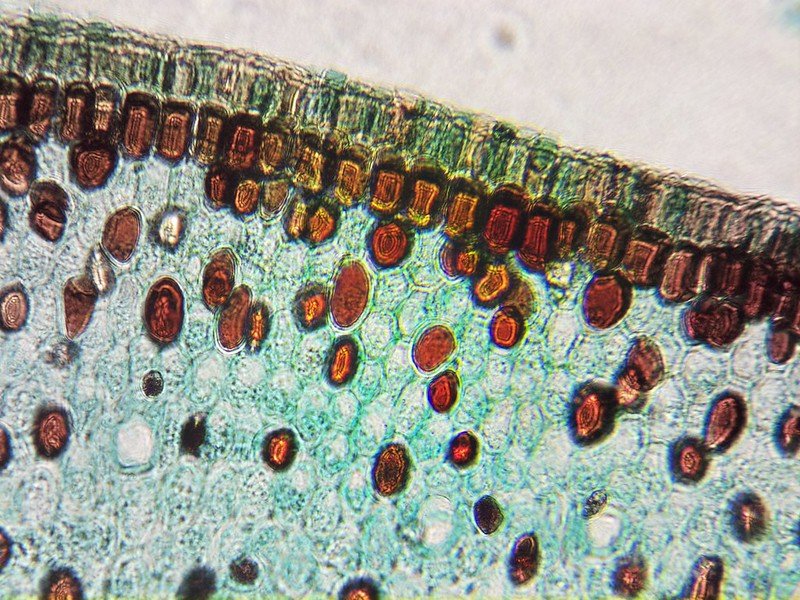
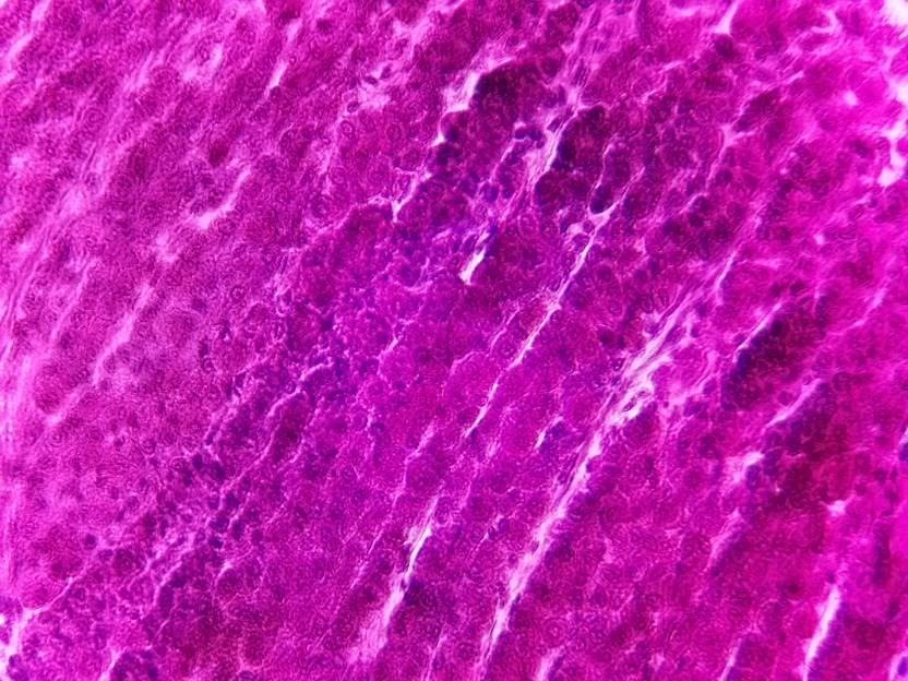
40x image using the microscope.
I’ve always had a fascination with building and engineering medical equipment. At the start of March, I decided that I wanted to play around with something I’ve seen pop up from time to time for year: The OpenFlexure Microscope. For this initial post, I am going to introduce what this project is, talk about my experience 3D printing the project and building it, and where I hope to go from here.
The goal of the OpenFlexure project is to make high precision mechanical positioning available to anyone with a 3D printer, the best part being that it’s completely open source. The main bodies are compliant mechanisms that are printed as 1 single object. This creates a “flexure” that can be bent in and out of shape to move the platform in the X, Y and/or Z direction.
Learn more about what compliant mechanisms are from this Mark Rober video!
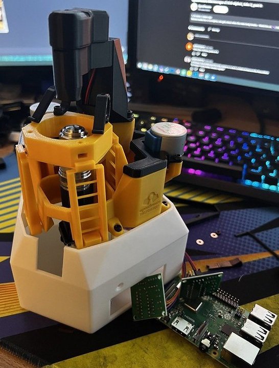
The initial flexure that I built is a motorized optical microscope. It combines the power of a Raspberry Pi, a Sangaboard (or Arduino) and 3 motors to create a very powerful, low cost microscope. It has a 12 x 12 x 4mm travel distance and you can view and interact with the microscope through a web interface.
Build
If you do not have any of the parts, a Raspberry Pi, nor an Arduino, you can expect to spend about $150 on this project. I had almost everything besides the lenses and a few odds and ends so I ended up spending very little on this build.
Bill of Materials
You can find the official BOM and build guide on their website.
Printing
The version I built the High-resolution microscope v7.0.0-beta1.
For the 3D printed parts, I used a Bambu Lab X1C. I printed all of the parts at 0.28mm Extra Draft, 15% fill grid, and Slice gap closing radius at 0.001. The total print time was about 10 hours and used about 350 grams of filament.
I have since tried reprinting the body at 0% infill with success so 15% fill was definitely too much. The only part that I’ve discovered needs to have a much lower layer height is the part that holds the objective. The part has threads and it seemed like 0.12mm layer height resulted in a solid thread for the objective. The 0.28mm version has a terrible thread fit.
Parts
I ordered 3 50mm acromatic doublet lenses from Surplus Shed for $7.50 each, plus $6 shipping. You only need 1 but I wanted to have a few extra incase I wanted to build more than 1 microscope. It shipped out the next day (Friday) and arrived Monday (3 days later).
I bought the 30mmx34mmx2mm O-Rings on Amazon (https://www.amazon.com/gp/product/B07ZDM58S8/ref=ppx_yo_dt_b_asin_title_o00_s00?ie=UTF8&psc=1)
I bought an AmScope 40x Achromatic objective for the microscope. I have since learned that the objective I bought was not a Plan objective. It’s about three times the price if you want one that is plan and I’ve been told this is important if you want a better quality image that is completely in focus across the sensor. I may upgrade to one soon to try out and compare.
I am using a Raspberry Pi 3 with an Arduino Mega and 3 28BYJ-48 stepper motors plugged into ULN2003 driver boards. I am using a standard Raspberry Pi Camera v2.
I bought these Optical Convex Condenser lenses from Amazon (https://www.amazon.com/dp/B0BR5PYPQB?psc=1&ref=ppx_yo2ov_dt_b_product_details 2). It just barely fits and will fall out if you bang the table so it seems 12.5mm may be too small and 13-13.5 may give a better fit.
For the LED, I printed the LED workaround and I am using a standard 5mm warm white 20mA/3-3.2V LED with a 150 ohm resistor.
I bought some 0.5mm white styrene sheets but they appear to be too thick because they block a lot of the LED’s light. Removing the sheet from under the LED did not seem to have too negative of an effect on the image.
I used 20mm instead of 25mm screws for the gears. I was not able to find any 25mm screws locally so I just ran with 20mm. They appear to work just find, but result in a slightly diminished scan range.
Assembly
Putting together the microscope was pretty straight forward and for the most part it was easy to follow along. I did need to reference the ‘livestream’ video once or twice to fully grasp what needed to be done. Overall it took 2-3 hours to put together but now that I’ve done it, I could probably get put together in about 30 minutes.
The Arduino workaround does not specify which pins are what, only that it uses pins 2-13. I would have liked to know that X is pin 2-5, Y 6-9, etc. and I had to guess and check. I am powering the motors using 5V out from the Arduino with success.
Software
I installed the Raspbian OpenFlexure full desktop on a 256GB SD Card. I have only interacted with the microscope over the web browser so it appears I should have went with the Lite version instead. The software is really great compared to a lot of other scientific software, but I think there is still a lot of issues and improvements that could be made.
The biggest issue I had was that it is not well documented what to expect from 40x images and that the focus distance to the slide is very close. It’s so close that I realized you needed to flip the slide upside down to achieve proper focus. This is not really a software problem but there are a lot more people than just me that have encountered this issue so I think as part of the initial use documentation, it would be great to have some information about that.
Initial Calibration
When I first launched the UI, this is what I was greeted with. The initial image was not promising but luckily it’s very easy to fix by running through the calibration settings.
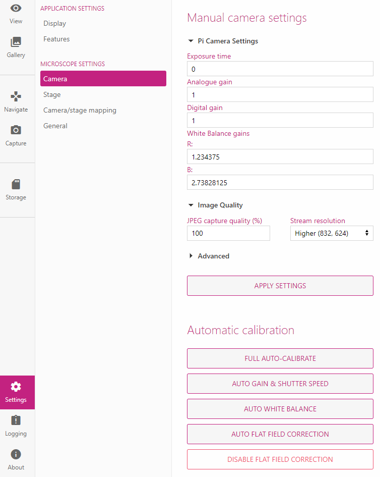
There are three main calibration settings: auto gain and shutter, auto white balance, and auto flat field correction.
They are pretty explanatory, but the auto gain will adjust how bright or dark the image is, the white balance will adjust who blue or orange the image is, and the flat field correction will uneven illumination, lens vignetting.
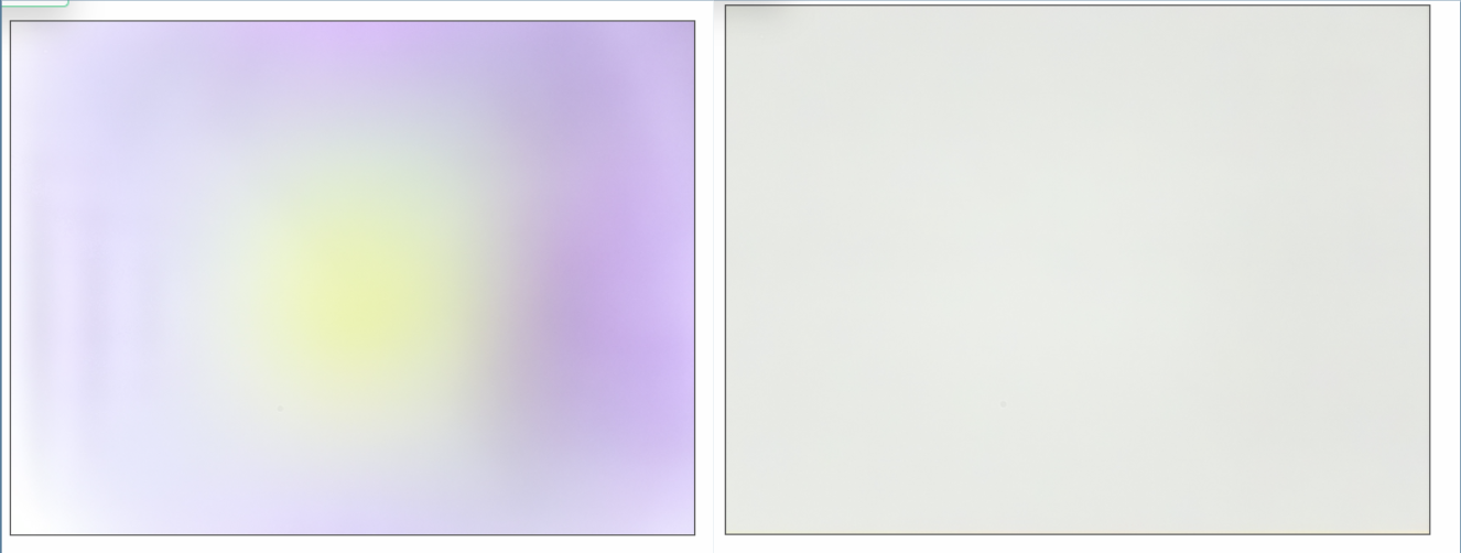
For the following image, the left is what the image looks like after auto gain & shutter and auto white balance, and the right is what the image looks like after auto flat field correction. This correction makes a huge difference.
Moving and Scanning
The two tabs you will spend the most time in are the Navigation tab and the Capture tab. In the navigation tab, you can move the microscope by either using the arrow keys and scroll wheel, or by manually typing in the coordinates into the Move-To section and clicking Move. The Step Size is used to change how many steps are taken when using the arrow keys and scroll wheel.
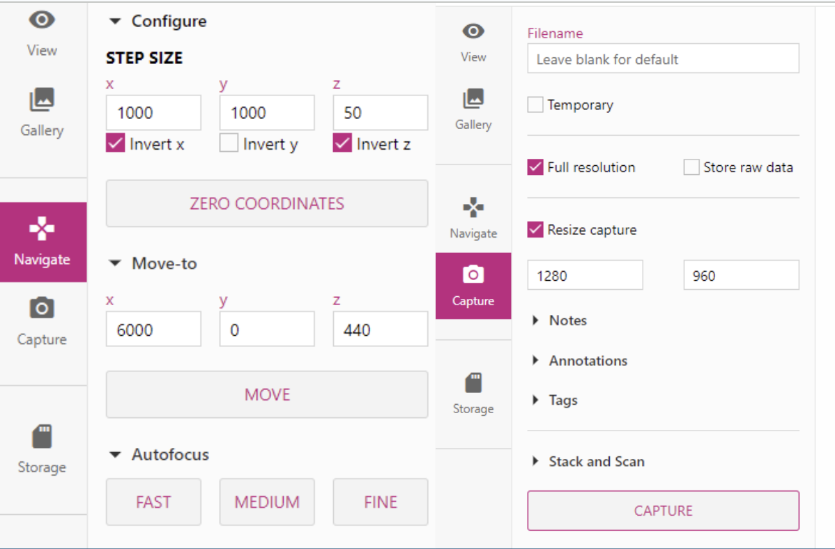
You also have access to three different auto-focus options. I’ve found that they do work but can miss focus a lot. They are also very limiting. The Medium and Fine only searches so far up and down so if your focus is past that, it won’t find it.
The following is an example issue I had with the auto-focus. The left I manually focused and the right I used the fast focus. You can see that the fast focus is pretty close but is just not there and as a result, it’s not sharp.
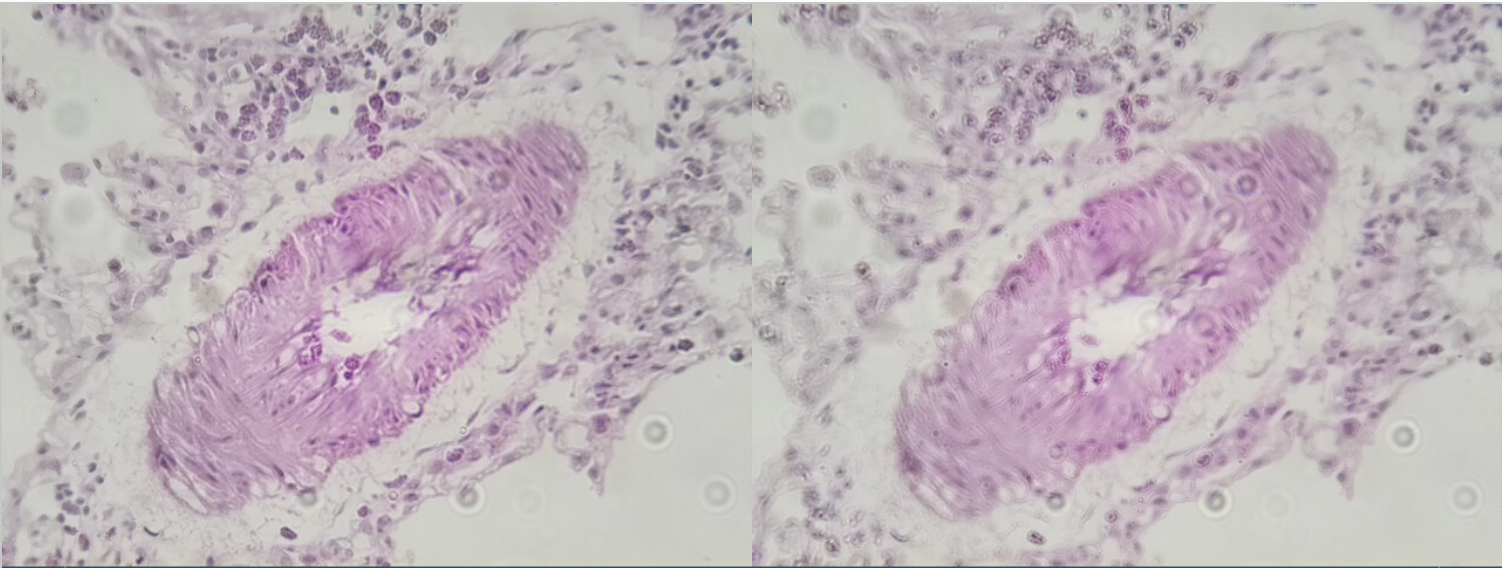
Left: Manual, Right: Fast Autofocus
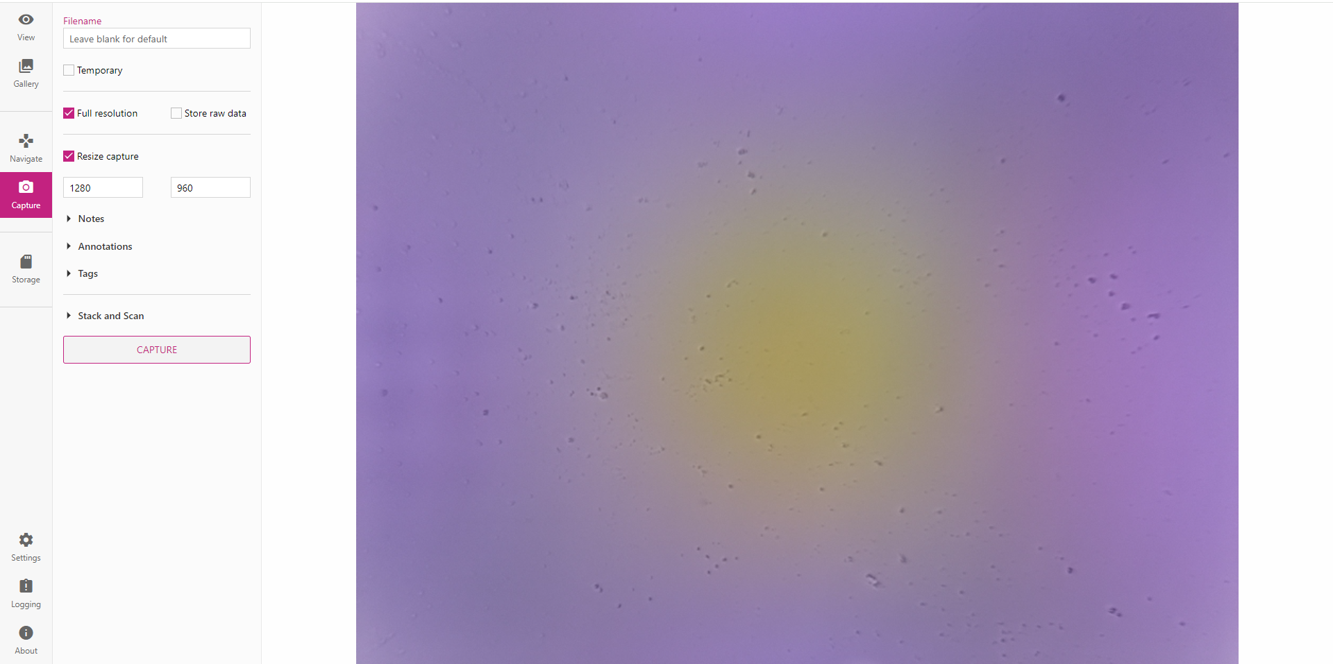
The capture section enables you to capture images and save them directly to the Pi for later viewing. You can also play around with the Stack and Scan options, which allows you to automatically scan through the image with quite a few different parameters.
The three main things you will change are the steps, autofocus, and scan style.
The step size will determine how large of a movement to make after each image. The steps is how many steps it will take in each axis. The autofocus options allows you to select which type of autofocus you want to preform before capturing each image.
There are three different types of scan styles: Raster, Snake, and Spiral.
The Raster style will start in the top left corner, move right x steps, then move back to the start y and move down y step size. I find that this is a lot of wasted movement and tend to stick with Snake instead. Spiral will use the starting position as the center and slowly snake outwards.
Below is an example of a Zea Seed I scanned using the scanning functionality then stitched together using OpenCV.
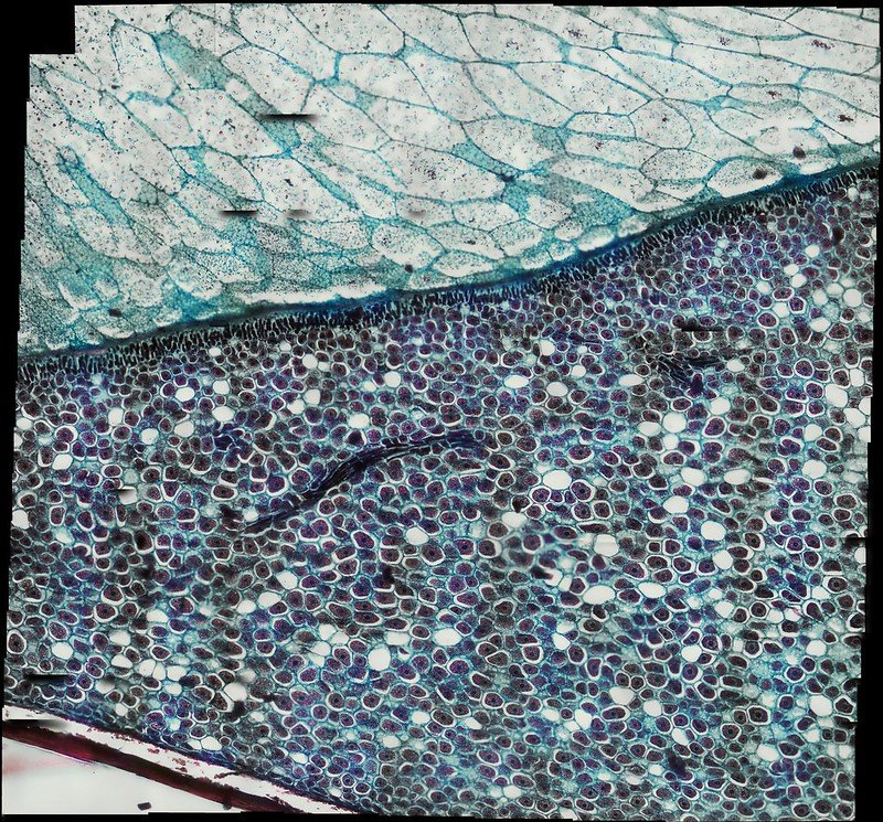
Zea Seed L.S.
x step-size 1200
y step-size 1200
x steps 16
y steps 16
Autofocus Fast
Scan Style Snake
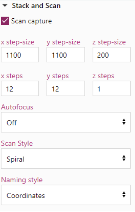
Below is another example of a stitched together image using the scanning method of a Tilia Stem.
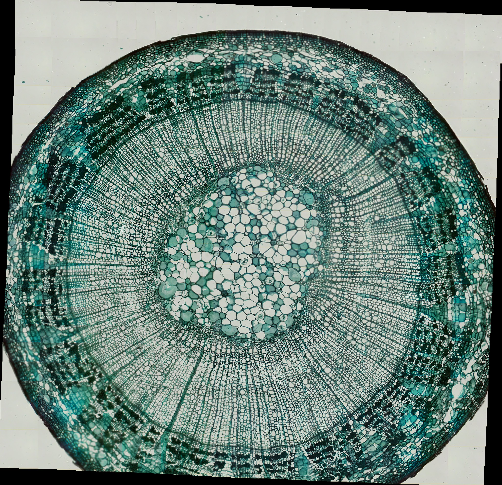
Tilia Stem CS
x step-size 1100
y step-size 1100
x steps 12
y steps 12
Autofocus Off
Scan Style Spiral
Conclusion
Overall, I am pretty impressed with everything. It was a lot of fun to build and tinker with and I was surprised with the quality of the images for a plastic microscope. I look forward to seeing how the project will continue to develop over the next few years.
My next project, I want to use the Delta version of the microscope to try and build a confocal laser scanning microscope.